CAN Bus Loopback Test with PCAN USB Interfaces
A loopback test is a useful way to check that a system and its data transmission hardware is working. For a controller area network (CAN) linked to a PC, a message loopback to the same test computer is simple to achieve if the PC has two CAN adapters. In this article two PEAK-System PCAN-USB CAN adaptors are use to perform a CAN loopback test on a PC.
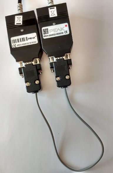
A Minimum of Two CAN Bus Devices are Required
The easy way perform a CAN bus loopback test on a PC (or other system) is to have two CAN devices talking to each other. The loopback test works by sending data on one CAN device and checking it is received on the other device, and vice versa. The steps for performing the loopback test for a CAN bus are:
- Create a two node CAN network.
- Send data on one CAN node and see if the same data is seen on the second node.
- Next do the reverse, send data on the second CAN node and see if the same data is seen on first node.
Creating a Two Node CAN Network
At its simplest, e.g. for bench testing, CAN bus wiring is very straightforward. It is a case of joining the two CAN wires from each node together correctly. The CAN high data line from one CAN node is connected to the CAN high data line of the next CAN node, and likewise for the CAN low data line. In this article the PEAK-System PCAN-USB adapters are used. These adapters use a DB9-type (9-pin D-Sub) male connector that conforms to the CAN in Automation (CiA) 303-1 specification for connector cabling. Note: Some CAN devices do not follow CiA 303-1 wiring (e.g. some arduino add-on boards), therefore check your device's instructions.
The basic CAN wiring for the DB9 connector is to join pins 7 (CAN+) together, and pins 2 (CAN-) together. For bench testing low baud rate CAN buses (100K baud or less) the network will usually work without a termination resistor. However, for higher speed networks and long cables, a 120 ohm termination resistor is required at each end of the CAN bus (wired between the CAN high and CAN low lines), see the CAN bus wiring article.
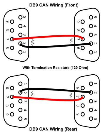
For the PCAN-USB devices two DB9 female sockets can be cabled together:
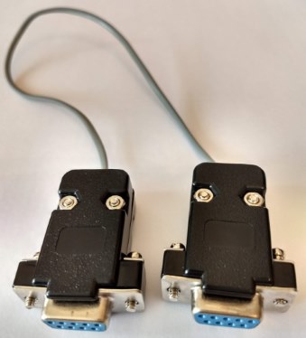
The two PCAN-USB adaptors can then be plugged together (as in the first picture) and then connected to two spare USB ports on the computer. It is also possible to use straight through DB9 cables, or ribbon cables fitted with 9-pin D-Sub Insulation Displacement Connectors (IDC) to connect PCAN-USB devices together:

Writing and Reading the CAN Data
A computers communications (COM) port is often used to read in data from CAN devices. If a device uses standard PC COM ports then a PC terminal program (e.g. PuTTY) can be used to read and write data. For the PEAK-System devices the software for the PCAN-USB hardware is available from the PEAK-System web support area. It includes:
- Windows drivers (installed by running PeakOemDrv.exe from the PEAK-System_Driver-Setup.zip download).
- PCAN-View, a CAN data traffic viewing and data packet transmission program. Good for perform basic CAN traffic capturing and viewing functions. (Copy PcanView.exe from the pcanview.zip download.)
With two CAN interface devices connected to the PC, it requires two copies of the software to be executed. For devices that communicate via standard COM ports, then two instances of a terminal program will be run. For the PCAN-USB devices two instances of PCAN-View will be running. Note: It is important to set the CAN baud rate of each device to be identical:
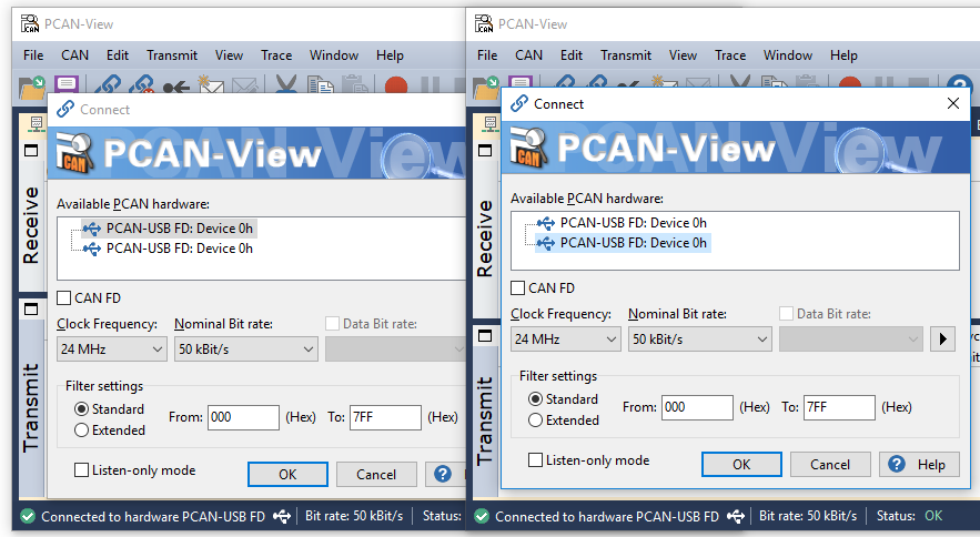
Finally Check that Data is Sent and Received
Send a message from one CAN device and ensure it is received on the other device. For devices that use standard COM ports see the instructions for the command sequences to send and receive the messages. For the PCAN-USB devices set up a new transmit message. The message is sent using the Space bar, or it can be set to repeat automatically.
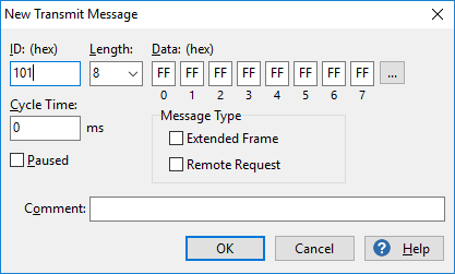
In PCAN-View the transmit and receive messages are viewed on the same screen:
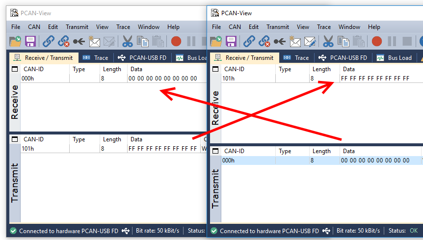
If no transmitted data is being seen, or transmission errors are reported, check that the cables are wired correctly, the network is correctly terminated (120 ohm resistors), and the baud rate settings of both CAN devices are identical.
See Also
- CAN bus wiring
- For a full list of the articles on Tek Eye see the full site Index
Comments
Rahul on 14th May 2021 at 09:16 am said: Can we use single PCAN USB for loopback?
Tek Eye on 14th May 2021 at 13:15 pm said: Hi Rahul. Yes, if another CAN node can be configured or programmed to replay a received packet, then a single PCAN USB can be used. A CAN network must always have at least two CAN nodes (devices) operating. If one of the devices is a PCAN USB, then the second CAN node must be able to immedaitely send out a duplicate of the packet it received. Thus, the second node must use a software program that immediately transmits a copy of the received CAN data packet (using the same CAN id for the perfect loopback).

Author:Daniel S. Fowler Published:


